Thermal Plant Description
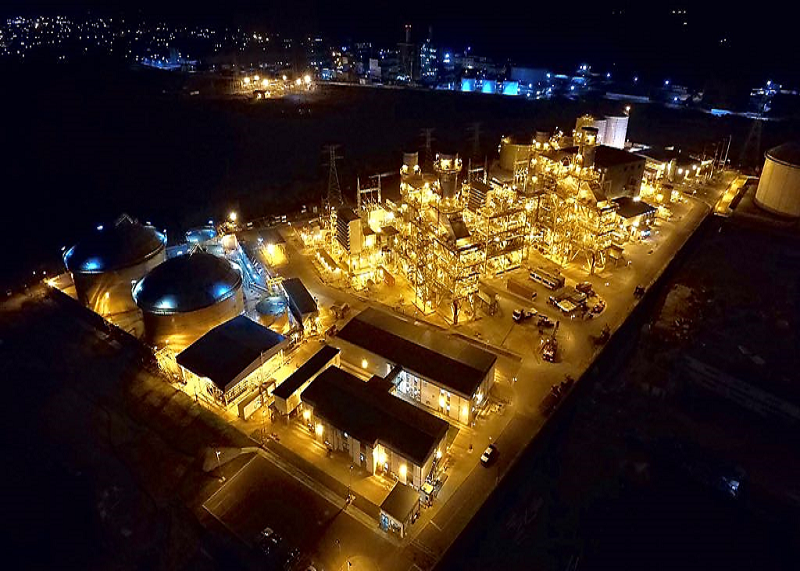
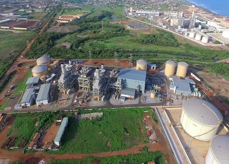
Cenpower Generation Ltd ('Cenpower') is a special purpose company set up to develop and build a 350MW Combined Cycle Gas Turbine (CCGT) plant at Kpone, Tema.
The KIPP Project is the first private sector Greenfield project financed Independent Power Plant Project in Ghana, funded by 6 commercial banks and 6 Development Finance Institutions with a 15-year debt tenor. The plant is designed for multiple fuel operation (natural gas, light crude oil and distillate) with natural gas as the primary fuel.
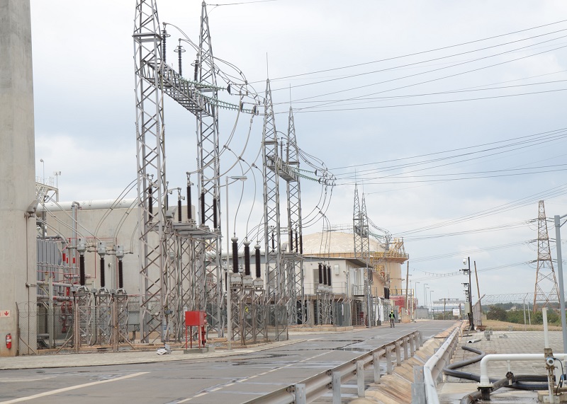
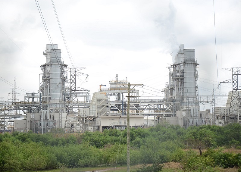
The project mainly comprises of two GE Frame 9E Gas Turbines, 2 NEM Heat Recovery Steam Generators (HRSG), One Siemens SGT800 steam generator and a once-through seawater cooling system as part of the main on-site facilities. The Project also comprises a 161kV Collector Substation, with an evacuation capacity of over 1,000MW which has been commissioned and has being handed over to the Ghana Grid Company (GRIDCo).
The KIPP project reached its financial close on 23rd December 2014. Construction and Commissioning of the Power plant is complete. The Commercial Operation Date was achieved on 10 June 2019.
The plant is of a modern, efficient and flexible design and meeting all relevant safety and environmental standards, capable of operating on natural gas, distillate fuel and light crude oil (LCO). Due to bypass stacks installed at the plant site, the operation of the plant on any of the fuels in simple cycle mode and in combined cycle mode is possible. Fuel gas will be supplied through a connection to the nearby West African Gas Pipeline (WAGP). Distillate fuel and LCO will be supplied from a fuel oil tank farm located approximately 2km from the Site.
Steam condensing is based on once-through cooling water system, utilizing intake of seawater and discharging to the sea. Demineralized water for process makeup and injection is produced on plant site from the extracted seawater by means of the Reverse Osmosis process in a Water Treatment Plant. A water treatment plant is sized to provide the required quantity and quality of potable and demineralized water for all process requirements.
The power generated by the plant will be supplied directly to the Electricity Company of Ghana (ECG), the main distribution utility through the Ghanaian electricity grid.
GT load is performed with constant GT exhaust gas mass flow in inlet guide vanes (IGV) in a closed position to a certain power level, but increasing exhaust gas temperature until the exhaust gas temperature is kept constant while the GT exhaust gas mass flow is increased by the opening of the GT IGV up to baseload.
By means of the GT exhaust energy, steam is produced in an HRSG.
Heat Recovery Steam Generator (HRSG)
The HRSGs are dual pressure HRSGs with natural circulation evaporator systems.
A condensate preheater heats the entire condensate flow approximately to the boiling temperature of the LP-system. Downstream of the condensate preheater the condensate flow is split to LP- and HP-/IP-stage within the first and second stage of feedwater pump (3x50% for 2 HRSGs). The LP-feedwater, extracted at first feed water pump stage is supplied to the LP-drum. From the drum, water is fed into the natural circulation evaporator. The resulting water-steam mixture returns to the drum, where it is separated by separators. The separated saturated steam is fed to the superheater and is heated further to LP-steam temperature.
From HP-stage of feedwater pumps, water is fed to the HP-systems of the HRSGs consisting of economizers, evaporator, drum and superheaters.
The HP-feedwater is pre-heated in the economizers and fed to the respective drum. Through the downcomers, water flows from the drum to the evaporator, where a portion is evaporated. Due to density differences, the resulting water/steam mixture returns to the drum and is separated by separators. The arising water is remaining in the drum and the separated, saturated steam is fed to the superheater section and is heated further to main steam temperature.
During combined cycle operation the generated HP-steam of both HRSGs is fed to the HP-part of the steam turbine by a common HP-main steam line and is expanded to low pressure.
The generated low-pressure steam is fed to the connection of the LP-steam supply towards the LP-section of the ST and the entire steam flow is completely expanded to condenser pressure in the LP-section of the ST.
Steam Turbine
The HP-main steam of the HRSGs flows to the HP-turbine section. The exhausted HP-steam is fed into the LP-turbine inlet and combines with inducted LP-steam produced by the HRSG’s LP-system. This combined steam flow is expanded in the LP-turbine section. The exhaust steam of the LP-turbine flows axially out of the steam turbine to the condenser. The ST drives its related generator.
Water-Steam Cycle
The water-steam cycle consists primarily of the condensate system, feedwater system and steam system. The condensate is extracted from the condenser hotwell and delivered to the CPH via condensate extraction pumps. The condensate is preheated in the common preheater of the HRSGs and transferred to the LP- & HP-drums via the three feedwater pumps.
The HP- and LP-steam generated in the HRSGs is fed via the steam systems to the steam turbine in the turbine building.
Cooling Systems
The turbine exhaust steam is condensed in a condenser. The condenser shell is axially exhausting the LP-turbine section and condenser is cooled with seawater once-through cooling by means of circulating water pumps.
The auxiliary service cooling water system is used to perform cooling of the auxiliary systems of GTG and STG and supply seawater to other parts of the Balance of Plant.
KIPP in Pictures


